INDUSTRIAL AI · INSTALLATION · COMMISSIONING
AI Pedestrian Detection Camera Installation: ROI, Placement & PLC Checklist
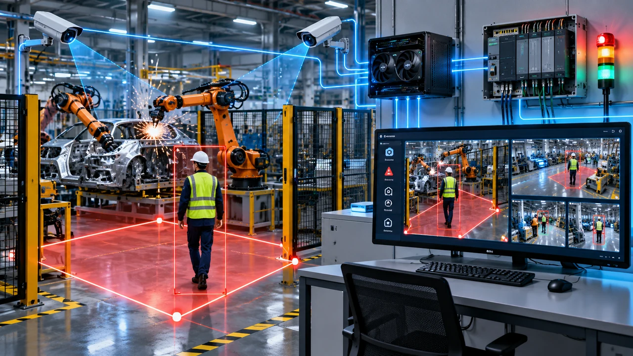
A pedestrian-detection model can be excellent and still fail on site if the camera is too high, the target becomes tiny at the far end, lighting changes across shifts, the ROI includes a reflective screen, or PLC fault behavior is never tested. This guide treats installation as an engineering and commissioning problem—not a “mount camera and adjust confidence” exercise.
Quick answer: how to install an AI pedestrian detection camera correctly
Start with the hazard and required response, not with the camera bracket. Mark the real detection zone, identify every pedestrian approach direction, choose a camera position that keeps people visible and large enough throughout that zone, stabilize lighting and focus, then configure the ROI around the actual decision area. After that, tune AI thresholds and confirmation timing using recorded edge cases. Finally, test the complete path from person → camera → AI → decision logic → PLC/alarm → reset, including camera-offline and communication-failure states.
If you need the broader system architecture first, see the AI pedestrian detection camera and system guide. If the system is already installed but producing nuisance alarms or missed people, use the false-alarm troubleshooting guide.
1. Define the safety and automation boundary before choosing camera position
The first installation mistake is treating “detect a person” as the whole requirement. In a factory, the useful question is usually more specific: which person, in which area, under which machine state, for how long, and what should the downstream system do?
Write the requirement in operational language before touching the AI settings. For example: “When a visible person is confirmed inside the robot-cell hazard ROI while the cell is in automatic production state, raise Human Detected to the PLC. When the AI service or camera stream is unhealthy, remove System OK and raise a fault.” This is much more testable than “camera should detect humans.”
Also separate a general AI detection function from a certified safety function. A conventional AI camera or GPU vision application should not be assumed to replace guarding, interlocks, safety laser scanners, light curtains, emergency stops or a safety PLC. If a detection is intended to contribute to machine stopping, the complete machine-safety architecture must be risk-assessed and validated for that use.
2. Perform a site survey around visibility, not just mounting convenience
A convenient wall or cable tray is not automatically a good analytics location. Walk the area from the camera’s perspective and list the conditions that change what the AI actually sees.
- Approach directions: Can a person enter from the left, right, rear, stairs, doorway or behind equipment?
- Occlusion: Do robot columns, weld fixtures, pallets, cabinets, parked vehicles or stacked material hide the lower or upper body?
- Lighting: Does sunlight enter at a particular hour? Are there welding flashes, reflective sheets, strong backlight, dark night-shift zones or IR transitions?
- Movement near the lens: Fans, curtains, hanging cables, insects, rain and vibration can create unstable visual conditions.
- Background: TV screens, posters with human figures, mirrors and windows can create human-like patterns or reflections.
- Target scale: At the farthest detection point, is the person still visually detailed, or has the camera been asked to cover too much area?
Vendor documentation supports this scene-first approach. AXIS Object Analytics advises correct mounting and warns against strongly top-down views for object classification. Digital Watchdog’s current AI analytics installation guidance emphasizes that mounting height, tilt, field of view and lens selection directly affect target detail; wider views cover more area but make people smaller. Hanwha Vision similarly documents camera-specific requirements for AI analytics that depend on mounting geometry and lighting. These values are product/application specific, so use them as evidence that geometry matters—not as universal numbers for every camera.
3. Camera placement: optimize target shape and usable detail
The practical goal is to keep the pedestrian recognizable across the entire decision zone. A camera image can look sharp to a human operator while still being poor for analytics because the target occupies too little of the frame or is heavily distorted at the edge.
Keep the critical zone away from extreme frame edges
Wide-angle lenses are useful for coverage, but targets near the outer image can be smaller and more distorted. Place the primary hazard zone closer to the central, optically useful part of the image when possible. If one camera has to watch a very wide floor area, ask whether two narrower views would produce better detection evidence than one panoramic view.
Avoid unnecessary top-down geometry
Many person-classification systems benefit when the camera can see a recognizable human profile rather than only the top of a helmet and shoulders. AXIS specifically cautions that looking down from above can make object classification harder. For some other analytics, vendors publish different preferred angles. That is why the correct installation method is: check the product guidance, then validate on the real scene.
Choose lens and distance together
Moving the camera farther away increases coverage but reduces target size. A longer focal length can recover target detail but narrows the field of view. Treat camera distance, lens, mounting height and tilt as one geometry problem instead of four independent settings.
Do not lock an arbitrary “perfect height” into your specification unless it is supported by the exact camera/analytics combination. For example, Hanwha publishes specific height, angle, distance and illumination recommendations for some AI functions, while i-PRO publishes different distance/view guidance for PPE analytics. The important engineering lesson is that every analytic has a valid scene envelope.
4. Measure the hardest detection point before finalizing the bracket
Commissioning should be driven by the worst useful view, not the easiest one. Identify the farthest valid pedestrian location, the most severe partial occlusion and the most difficult lighting state. Capture still frames from those conditions and inspect them at the resolution actually used by the AI pipeline.
A simple field method is to mark three validation points:
- Near point: closest valid position inside the decision zone.
- Nominal point: where pedestrians most commonly travel.
- Far/edge point: hardest position that must still count.
At each point, walk toward, away from and across the camera. Repeat with realistic PPE, clothing colors and carried objects. If the far point fails repeatedly, do not immediately lower confidence. First improve the view: reduce coverage, change focal length, change mounting position, add a second camera or alter the ROI so the system is not required to make a safety-relevant decision from inadequate imagery.
5. Design the ROI as a decision boundary, not a drawing exercise
ROI configuration is where a general person detector becomes a site-specific industrial rule. A good detector may correctly identify a worker outside the dangerous area; the ROI decides whether that detection matters.
Main ROI
The main ROI should cover the actual restricted or monitored region—not the entire image simply because the camera can see it. Hanwha’s guidance for AI analytics similarly recommends limiting the detection area to the meaningful walking region rather than blindly using the whole camera view.
Ignore zones
Use ignore/exclusion zones when the main ROI unavoidably includes visual regions that should never create a decision: reflections, safe platforms, adjacent walkways, monitor screens, windows or inaccessible areas.
Dynamic ROI
Some industrial applications need the effective hazard zone to change with machine state. For example, a robot path, transfer carriage or moving fixture can change which part of the image is dangerous. In that architecture, the PLC may select an ROI state while the vision system evaluates only the enabled zone. Treat ROI-state communication as part of the control interface and test every state transition.
Test the ROI boundary itself
Do repeated walks just outside, directly on and just inside each ROI edge. The point is not only to prove that the center works; it is to understand exactly where the software changes from “visible person” to “actionable person.” Record edge cases and confirm that the displayed overlay matches the decision logic.
6. Lock image quality before tuning AI confidence
Confidence thresholds cannot repair a bad image. Before AI tuning, verify:
- focus remains sharp at the critical target distance;
- shutter/exposure does not turn walking people into heavy motion blur;
- backlight and glare do not erase body detail;
- night/low-light mode does not change the scene so drastically that the model behaves differently;
- WDR, gain, noise reduction and sharpening are not creating unstable artifacts;
- the camera mount is rigid and vibration-free;
- the RTSP profile used by the AI is the intended resolution, codec and frame rate.
Lighting requirements are analytics-specific. Hanwha, for example, specifies minimum illumination for particular AI functions. Do not copy one vendor’s lux figure into another product’s acceptance criteria; instead measure and document the real scene and verify performance across the lighting range the installation must support.
7. Build a stable RTSP and compute pipeline before judging the model
A frozen or delayed stream can look like an AI failure. Separate camera health from inference quality.
| Layer | What to verify | Typical failure symptom |
|---|---|---|
| Camera | Power, link, focus, exposure, encoder | No image, blur, severe lighting variation |
| Network | Packet stability, switch load, cable, IP conflicts | Stutter, reconnects, delayed frames |
| RTSP decoder | Correct stream, stale-frame detection, reconnect logic | Last frame remains visible after camera loss |
| Inference | GPU/CPU load, frame queue, model latency | Bounding box lags behind real movement |
| Decision logic | ROI, confidence, tracking, confirmation timer | Chatter, delayed clear, nuisance event |
| PLC interface | Heartbeat, System OK, fault behavior, timing | AI detects correctly but machine logic receives wrong state |
For multi-camera systems, intentionally disconnect one camera while the others are running. One failed channel should not silently freeze the entire application. The HMI should make stale/offline status obvious and the configured fault output should behave exactly as documented.
8. Tune confidence, tracking and confirmation time in the correct order
Do not tune five variables at once. Use this order:
- Fix the scene and camera geometry.
- Fix ROI and ignore zones.
- Establish a reasonable detection confidence baseline.
- Enable tracking or temporal association if the pipeline supports it.
- Add a confirmation timer only after you understand one-frame and short-lived detections.
- Measure added latency end to end.
A short confirmation window can reject transient detections, but it also delays the output. That trade-off must be measured against the real application. If a system is connected to PLC logic, the relevant number is not “model inference time”; it is the total time from a real person entering the defined condition to the PLC receiving the intended signal.
9. Engineer PLC signals for normal, detected and failed states
A useful integration normally communicates more than one bit. Exact addresses depend on the project, but the logical interface often benefits from signals such as:
- Human Detected — confirmed actionable detection;
- System OK — application, required cameras and communication healthy;
- System Fault — one or more required health checks failed;
- Heartbeat — toggled or updated so the PLC can detect a frozen application;
- ROI/Mode input — optional PLC-to-AI state selection.
The important design question is what happens when confidence disappears. If the camera cable is pulled, the AI process crashes, the PC freezes or PLC communication drops, the system must move into the documented fault behavior rather than leaving an old “safe” state latched indefinitely.
10. Use a commissioning test matrix instead of a demo walk
A single person walking through the center of the frame proves almost nothing. Use repeatable test cases and record pass/fail evidence.
| Test | Method | Expected evidence |
|---|---|---|
| Center entry | Walk through nominal path | Stable detection and correct PLC output |
| Far edge | Walk at farthest required point | Detection remains reliable at worst target scale |
| ROI boundary | Walk just outside / on / inside edge | Decision changes at intended zone boundary |
| Partial occlusion | Pass behind realistic fixture or pallet | Known behavior documented; no hidden assumption |
| Multiple people | Two or more people enter with overlap | No unexpected suppression or unstable event state |
| Different directions | Approach, leave and cross the view | Required directions validated |
| Lighting change | Day/night or process-light state | Detection quality remains within acceptance criteria |
| Reflection/background | Expose known reflective/display area | No actionable false event |
| Camera disconnect | Remove required stream | Offline state and fault logic occur correctly |
| AI service stop | Stop the inference application | Heartbeat/System OK fail as designed |
| PLC communication loss | Interrupt link | Fault behavior matches design |
| Restart recovery | Restart camera/app/PC | System returns only after health conditions are satisfied |
11. Acceptance criteria should include misses, false alarms and latency
“It works” is not a commissioning criterion. Define the evidence you will keep:
- number and type of required test scenarios;
- which scenarios passed, failed or require an operational limitation;
- recorded false-positive cases;
- recorded missed-detection cases;
- measured end-to-end detection-to-PLC timing;
- camera offline detection time;
- restart/recovery behavior;
- final camera position, lens/FOV, ROI screenshot and configuration revision;
- software/model version and threshold values used during acceptance.
This baseline matters because a future camera move, firmware change, model update, lens adjustment or factory-layout change can alter behavior. Without a commissioning baseline, teams often discover regression only after nuisance alarms or a missed event appears in production.
12. Common installation mistakes that destroy AI performance
- Covering too much floor with one camera: people become tiny at the far end.
- Mounting for CCTV aesthetics instead of analytics: the view looks wide and clean but the target geometry is poor.
- Using the entire frame as ROI: safe walkways and reflections become part of the decision.
- Lowering confidence to compensate for poor placement: this often increases nuisance alarms.
- Ignoring stream health: a stale image can remain on screen while detection is no longer live.
- Testing only in daylight: night shift or process lighting behaves differently.
- Testing only one person in the center: edge, occlusion and multi-person cases remain unknown.
- Sending only a detection bit to PLC: the PLC has no independent indication that the AI system is alive.
- No failure-state test: camera/network/application faults are discovered after deployment.
- No change control: a camera is bumped or ROI edited later and the original acceptance is no longer valid.
13. Installation checklist for field engineers
- Document hazard/monitoring objective and required downstream action.
- Mark pedestrian paths and all valid entry directions.
- Identify occlusion, glare, reflections, vibration and lighting changes.
- Select camera position and lens based on the hardest required target view.
- Verify focus/exposure using the actual AI stream.
- Define main ROI only around the actionable area.
- Add ignore zones for irrelevant visual regions where needed.
- Validate ROI edges with repeated walking tests.
- Confirm camera/RTSP health monitoring and stale-frame handling.
- Tune confidence and temporal confirmation one variable at a time.
- Measure total detection-to-output latency.
- Test Human Detected, System OK, Fault and heartbeat logic.
- Disconnect camera/network/PLC intentionally and verify failure behavior.
- Run the full commissioning matrix across relevant lighting and operating states.
- Save screenshots, test evidence, final configuration and software/model version.
14. When one camera is not enough
Add another camera when the required zone cannot be made visually reliable from one view. Typical reasons include deep occlusion behind machinery, a long narrow area where the far target becomes too small, multiple entrances with conflicting view angles, or a scene where one camera cannot avoid severe backlight.
Two well-designed views can be more valuable than one very wide image. The architecture can treat them as independent detection channels or combine them at the decision layer, depending on the application. What matters is that the logic is explicit and tested.
15. Related Xenors engineering guides
- Pedestrian Detection AI Camera & System for Factory Safety — complete system architecture, multi-camera AI, ROI and PLC overview.
- AI Pedestrian Detection False Alarms: Causes, Testing & Fixes — troubleshooting once the system is running.
- Forklift AI Camera: Pedestrian Detection & Auto Stop Guide — vehicle-specific pedestrian detection architecture.
- Connecting Edge AI Vision to PLCs — PLC handshake and integration concepts for edge vision systems.
FAQ
Where should an AI pedestrian detection camera be installed?
Choose a position where the full required pedestrian path is visible, targets remain large enough across the zone, lighting is stable and occlusion is controlled. Validate the exact position with repeated walking tests before final handover.
Should an AI camera look straight down from the ceiling?
Not by default. Some object-classification analytics perform worse with steep top-down views. Follow the exact product guidance and validate human shape and target detail in the real scene.
How should ROI zones be configured?
Limit the decision ROI to the real hazard or monitoring area. Exclude reflections, screens, adjacent safe walkways or irrelevant regions with ignore zones where supported, and test each ROI boundary.
How do you commission an AI pedestrian detection camera?
Use a documented test matrix covering distance, direction, ROI edges, occlusion, lighting, multiple people, camera loss, AI failure, PLC communication loss and restart recovery.
Can an AI camera directly stop a machine?
A general AI camera should not automatically be treated as a certified safety function. Machine stopping requires a suitable risk assessment and validated control architecture with safety-rated elements where required.
How should PLC communication be tested?
Test normal detection, clearing, health/heartbeat signals and every relevant failure state. Measure the real end-to-end response rather than relying only on model inference speed.
Sources and technical references
The installation principles above are informed by vendor documentation and field literature, while all product-specific numeric recommendations remain specific to those products/applications:
- AXIS Object Analytics — mounting and scene considerations
- Digital Watchdog — Camera Installation Best Practices for AI Analytics
- Hanwha Vision — AI camera installation guidance
- i-PRO — Safety Vest & Helmet Compliance App installation guidance
- Field study on implementation and adoption of AI camera pedestrian detection on construction sites
- Adaptive Zone Monitoring for Industrial Safety — YOLO, PTZ, HMI and PLC integration
Final commissioning rule
The best AI pedestrian detection installation is not the one with the highest demo confidence score. It is the one whose camera view, ROI, health monitoring, AI timing, PLC interface and failure behavior have all been tested against the real operating conditions and documented well enough to repeat after any future change.